Materials
RaspberryPi Zero W
Serial Breakout
TMP36 temperature sensor
Log Scale Analog Light Sensor
OLED Screen
microUSB cable
Jumper wires
Process
My original plan was to create a device that would track the amount of light in a specific phone booth. I had hopes that I could make assumptions of how the space was being used, and have the device then send Hue Light values to a lighting fixture I am working on that would be installed in said phone booth.
Setting up the raspberry Pi again was a challenge for me. I thought I properly created a backup image of the pi, but it turns out I corrupted my SD card somehow. Troubleshooting that and then acquiring a second SD card for the project took some time away from getting the pi to be actually sending sensor readings to the server.
Once it was time to get readings, the log scale analog light sensor I was using did not seem to return values that made sense to me within the pi. I then thought using the Arduino library to give me intelligible lux readings compared to the raw values would provide a decent baseline for what to expect the pi to return. I tried shining my phone’s flashlight and then covering the sensor completely to see how the values would change, but my test did not seem too fruitful.
Another day passed without sending actual data to the server, so I decided to use the TMP36 temperature sensor that Tom uses in his example. I wanted to use the humidity sensor also in the example, however the shop did not have any for rent.
I tried to get the OLED screen to work, but it kept on returning errors. I plan on continuing to troubleshoot this, but I decided that posting the temperature readings at the anticipated intervals should be prioritized.
Throughout the week, I received coding help from Sam, Name and Cy. Last night before I left the floor, I verified that my crontab was sending readings every 5 minutes. When I checked the readings this morning, I saw that I was sending my readings multiple times within the minute. I believe I am experiencing the same issue that Sam is having - a mixup between the .js file and crontab.

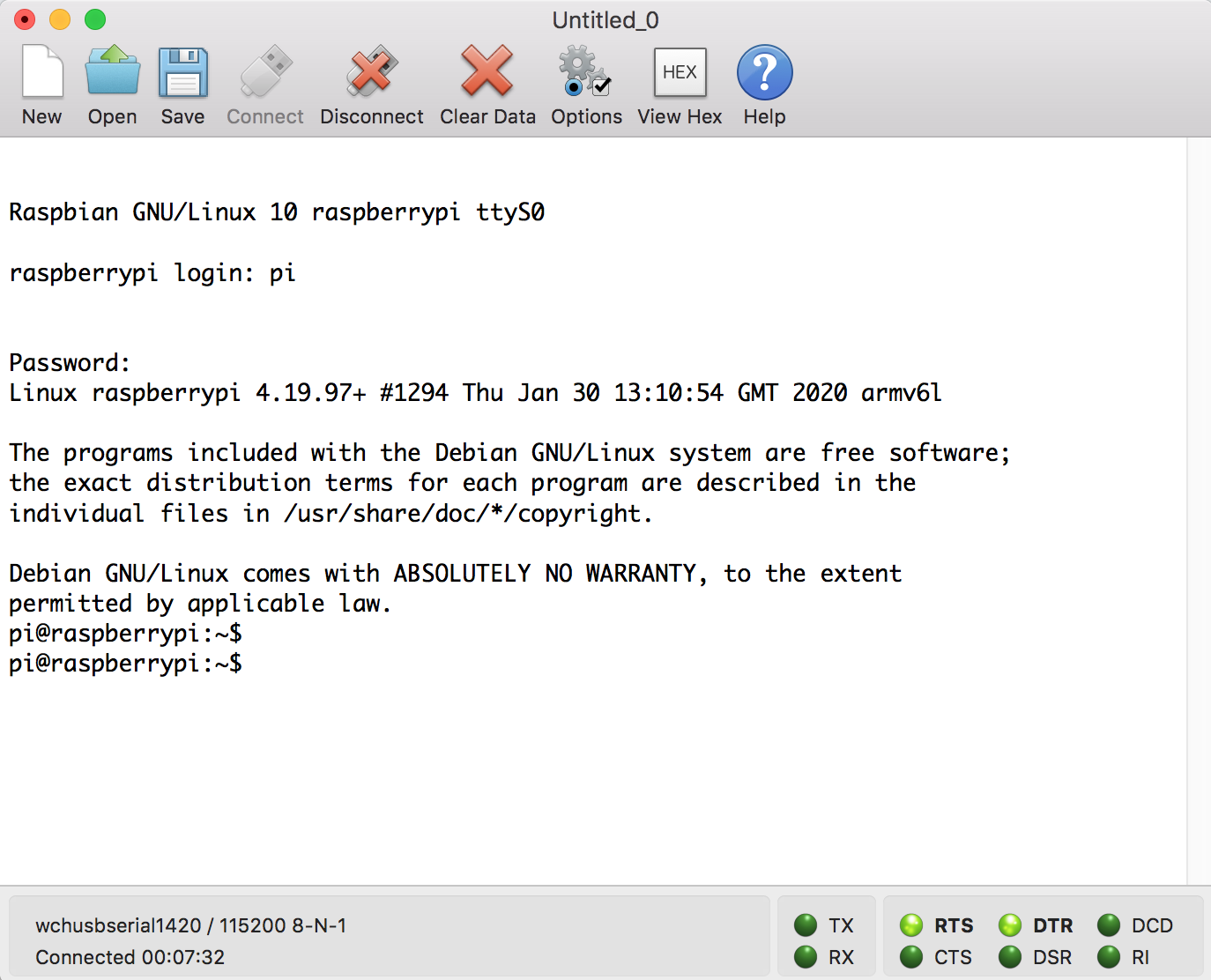
The response I received after reloading my backup image of the pi. Suspicious looking…

Unsteady readings with the Log Scale Analog Light Sensor and its Arduino library.

Not much difference between shining a flashlight vs covering the sensor completely.

Tinkering around with the screen after making sure that my script was successfully sending data to the server. In the end, I removed the OLED screen.

Odd error… my curl request did not return a complete list of transactionIDs.

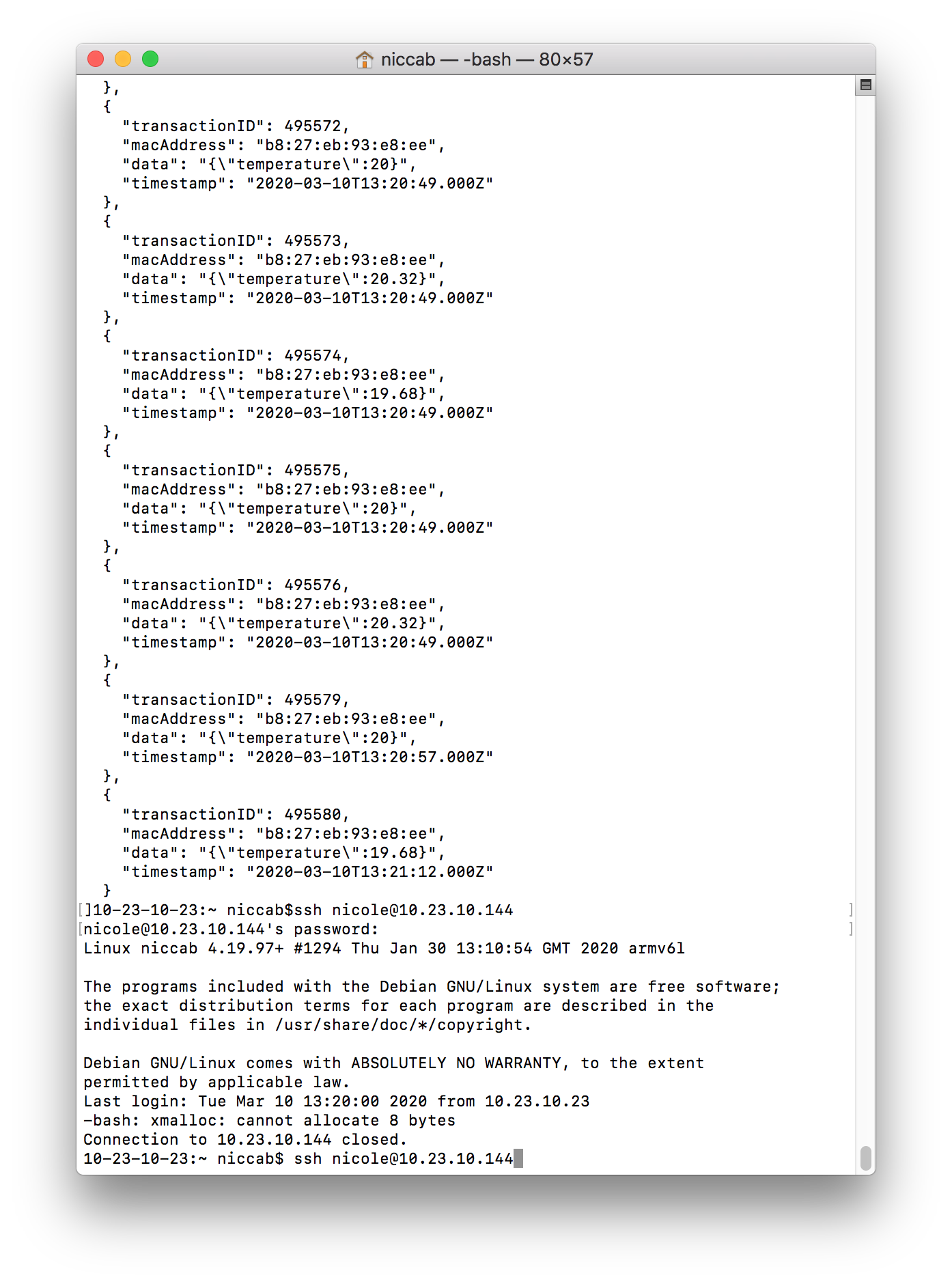
Sending multiple readings per minute. Unable to make edits to the .js over SSH.